
Many hours in
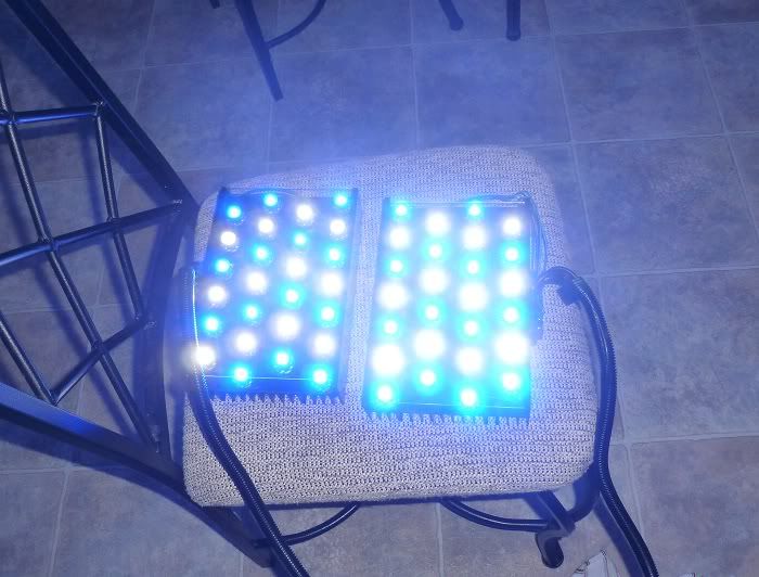
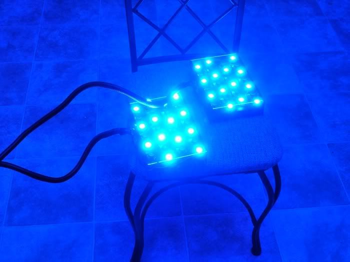
I have some good progress to report since last I left off. After the lenses dried on the lights I made sure they were all securely in place. *Tip: make sure to use enough silicone if you attach your lenses this way, I had a few wigglers that needed some extra sealant which I applied with a toothpick.
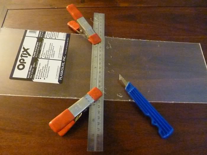
After all the LEDs were in place and wired in strings it was time to cut my splash guard. I went down to Lowes and bought standard 1/8" plexiglass and had them cut a 5 7/8" x 18" strip for me which I'm happy to report they were accurate enough on. Then when I got home I used my scoring tool to cut that in half again for two identical 9" splash guards which fit like a glove.
With that done I set aside the lights and moved on to assembling the power supply. I made several mistakes here which hopefully this thread leads others to avoid. I bought two of Radioshacks largest project enclosures, which were far too tight of a fit for me to be comfortable with.
So I returned the project enclosures and went to Hobby Lobby and bought a display box intended for displaying model cars. This seemed like a great idea, the plastic would be easy to cut to make ventilation holes, and there was plenty of room to add in the terminals I wanted to use for PWM dimming.
I sanded the inside of the display so I could paint it and make it look decent. But when I got it assembled my failure became all to apparent to me.
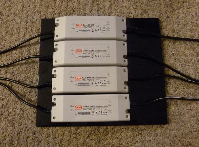
In my opinion this box was large, ugly and unwieldy, since I despised this enclosure and scrapped the entire top, I wound up just using small brass nuts and bolts to secure the drivers to the back plate and went back to the drawing board on how I would wire things up.
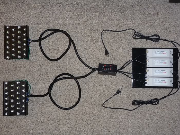
After redesigning my driver setup it was time to dial in the current on the drivers so that I wouldn't blow out my precious new LEDs the moment I plugged them in.
It is very easy to find instructions online about how to dial in the ELN 60-48D and the beginning steps are all the same. I found the covers to be difficult to remove and was scared of breaking them, this is not the case however and you just have to be brave and pull the top off like you mean it.
Next use a Phillips screwdriver to GENTLY turn the SVR2 knob counter clockwise until it stops. These little knobs are in no way rugged, so be careful. The SVR2 is the white knob in the corner which you'll see in the following picture.
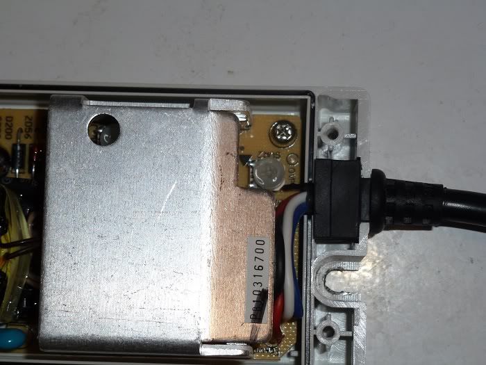
Once you've turned down the SVR2, the instructions were less clear for the 60-48P model which I decided to use. I have yet to get my Reef Angel and was not sure what I could use as a PWM source to turn the drivers on and let me check the current. Fortunately a simple answer is you can just use a 9V battery, just hook the battery to the blue and white leads coming out of the driver and you're ready to get adjusting!
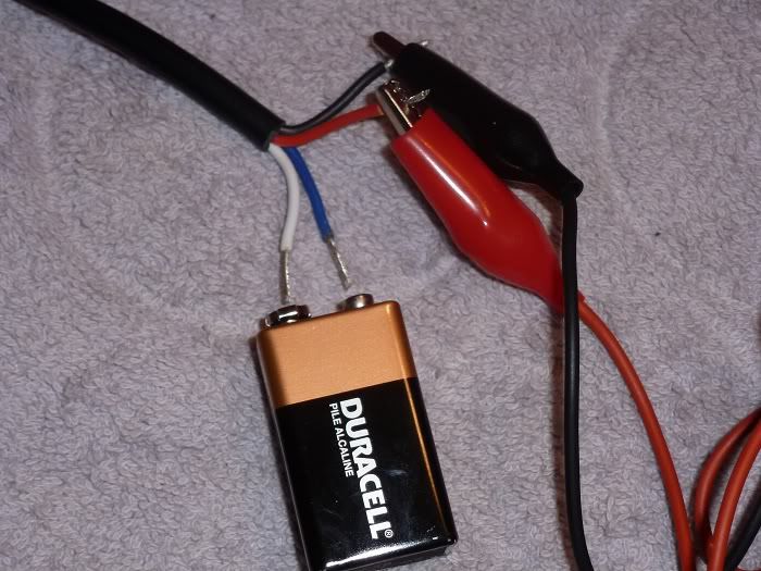
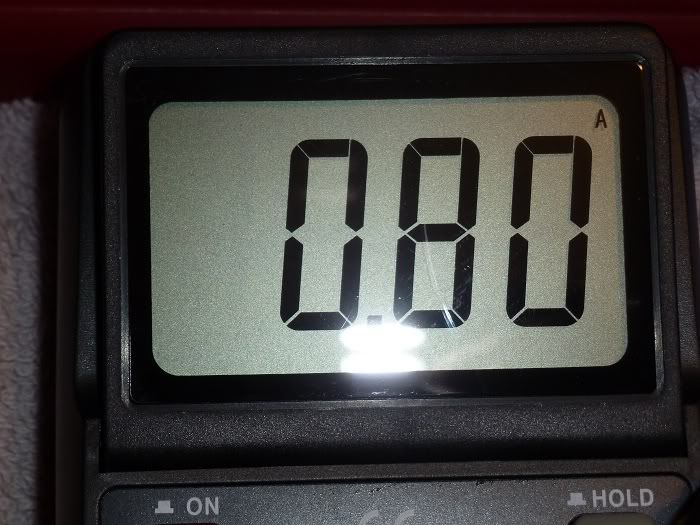
My experience was that with the SVR2 turned fully down the amperage came in between 200ma and 300ma. Turn the knob GENTLY and slowly until you reach your desired output current (I chose 800ma to give myself some overhead on the 1A max on the XT-Es).
In addition to checking your amperage, this is a great opportunity to verify that your drivers are coming in at the 48V they should be. Better safe than sorry after all.
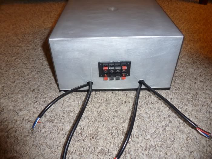
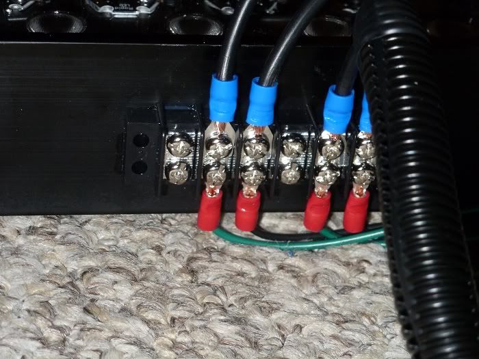
After getting the current all set it was time to start wiring these bad boys up! I wanted to make a terminal box to make hooking up the PWM leads from the Reef Angel super easy. I used a small project box and and 8-position push-release speaker terminal from Radioshack to make the box. At this point keeping wires and terminal positions straight became a more serious concern. My best friend was a silver Sharpie that I could use to write on basically anything. I advise finding a labeling system that works for you and being liberal with your labeling.
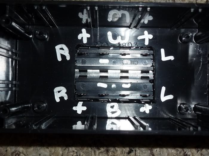
Inside my PWM hook-up Terminal
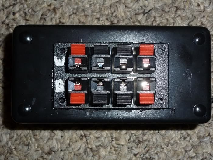
The outside of my PWM hook-up Terminal
I wanted to make things easy to take apart so I used female spade connectors to make hooking up the PWM input leads to the flat plugs on the back of the speaker terminal. I was really pleased with how easy this made assembly and even more pleased that I didn't have to solder anymore because dang it I was tired of soldering.
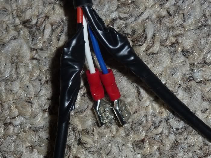
If I could go back in time I would have used more crimping connectors. They are excellent time savers, look better than hand-spliced connections, and I am now in love with them.
I have some good progress to report since last I left off. After the lenses dried on the lights I made sure they were all securely in place. *Tip: make sure to use enough silicone if you attach your lenses this way, I had a few wigglers that needed some extra sealant which I applied with a toothpick.
After all the LEDs were in place and wired in strings it was time to cut my splash guard. I went down to Lowes and bought standard 1/8" plexiglass and had them cut a 5 7/8" x 18" strip for me which I'm happy to report they were accurate enough on. Then when I got home I used my scoring tool to cut that in half again for two identical 9" splash guards which fit like a glove.
With that done I set aside the lights and moved on to assembling the power supply. I made several mistakes here which hopefully this thread leads others to avoid. I bought two of Radioshacks largest project enclosures, which were far too tight of a fit for me to be comfortable with.
So I returned the project enclosures and went to Hobby Lobby and bought a display box intended for displaying model cars. This seemed like a great idea, the plastic would be easy to cut to make ventilation holes, and there was plenty of room to add in the terminals I wanted to use for PWM dimming.
I sanded the inside of the display so I could paint it and make it look decent. But when I got it assembled my failure became all to apparent to me.
In my opinion this box was large, ugly and unwieldy, since I despised this enclosure and scrapped the entire top, I wound up just using small brass nuts and bolts to secure the drivers to the back plate and went back to the drawing board on how I would wire things up.
After redesigning my driver setup it was time to dial in the current on the drivers so that I wouldn't blow out my precious new LEDs the moment I plugged them in.
It is very easy to find instructions online about how to dial in the ELN 60-48D and the beginning steps are all the same. I found the covers to be difficult to remove and was scared of breaking them, this is not the case however and you just have to be brave and pull the top off like you mean it.
Next use a Phillips screwdriver to GENTLY turn the SVR2 knob counter clockwise until it stops. These little knobs are in no way rugged, so be careful. The SVR2 is the white knob in the corner which you'll see in the following picture.
Once you've turned down the SVR2, the instructions were less clear for the 60-48P model which I decided to use. I have yet to get my Reef Angel and was not sure what I could use as a PWM source to turn the drivers on and let me check the current. Fortunately a simple answer is you can just use a 9V battery, just hook the battery to the blue and white leads coming out of the driver and you're ready to get adjusting!
My experience was that with the SVR2 turned fully down the amperage came in between 200ma and 300ma. Turn the knob GENTLY and slowly until you reach your desired output current (I chose 800ma to give myself some overhead on the 1A max on the XT-Es).
In addition to checking your amperage, this is a great opportunity to verify that your drivers are coming in at the 48V they should be. Better safe than sorry after all.
After getting the current all set it was time to start wiring these bad boys up! I wanted to make a terminal box to make hooking up the PWM leads from the Reef Angel super easy. I used a small project box and and 8-position push-release speaker terminal from Radioshack to make the box. At this point keeping wires and terminal positions straight became a more serious concern. My best friend was a silver Sharpie that I could use to write on basically anything. I advise finding a labeling system that works for you and being liberal with your labeling.
Inside my PWM hook-up Terminal
The outside of my PWM hook-up Terminal
I wanted to make things easy to take apart so I used female spade connectors to make hooking up the PWM input leads to the flat plugs on the back of the speaker terminal. I was really pleased with how easy this made assembly and even more pleased that I didn't have to solder anymore because dang it I was tired of soldering.
If I could go back in time I would have used more crimping connectors. They are excellent time savers, look better than hand-spliced connections, and I am now in love with them.
")